Wind decides how many times we drill your roof
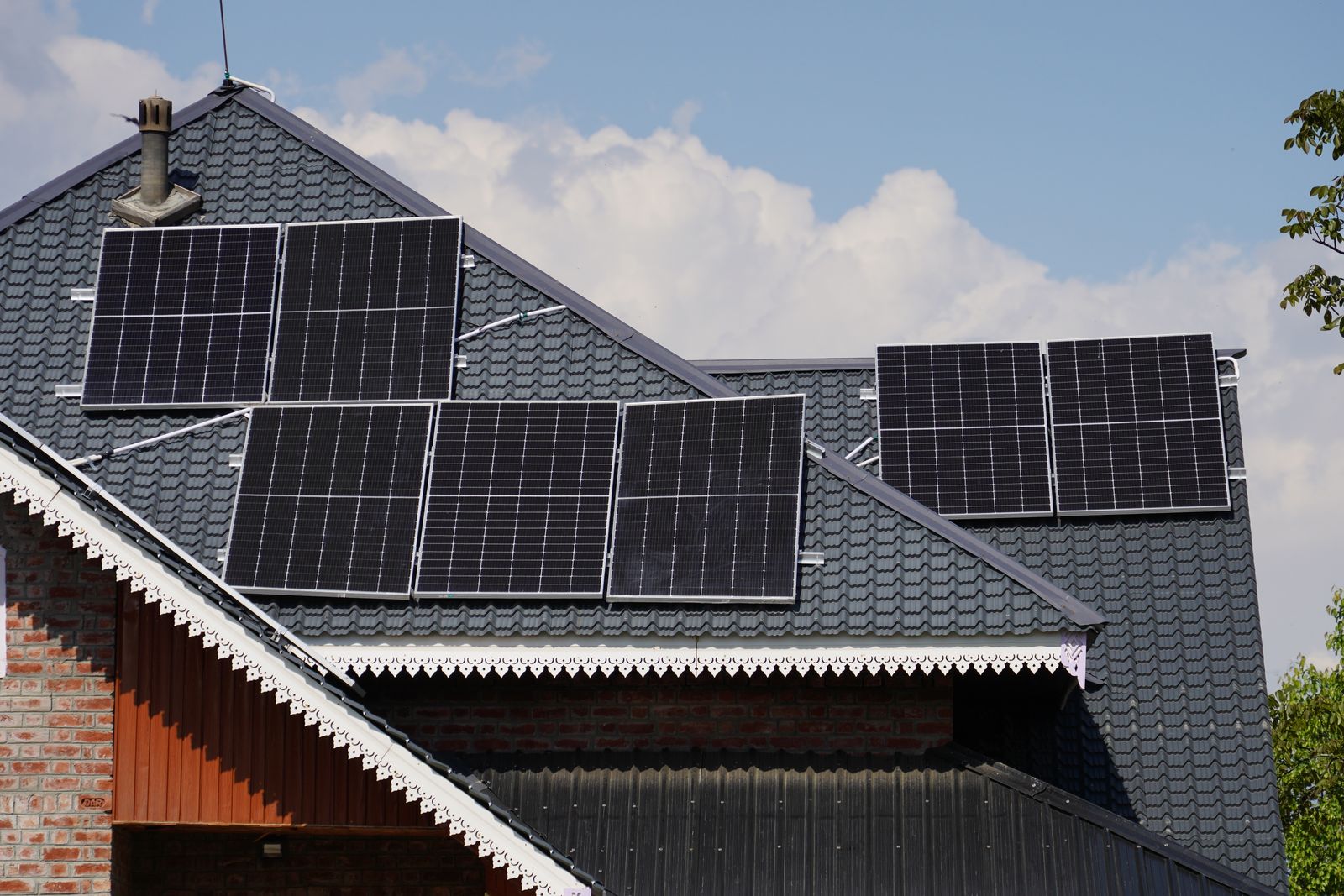
Exposure category, roof zone and design wind speed set the suction on every module. That number, not the weight of the array, sets the spacing between attachments.
Attachment spacing model
Move the inputs and watch the spacing change. Every step of the arithmetic is printed underneath.
Fresno County risk category II is 96 mph. Coastal and mountain sites run higher.
- Velocity pressure qh
- 18 psf
- Net uplift
- 28.5 psf
- Max attachment span
- 50 in
- Attachments
- 18
Governed by wind uplift at 28.5 psf
Spacing is set by the load, and sits inside the racking maker's allowable range.
The method, written out
- Velocity pressure. qh = 0.00256 x Kz x Kzt x Kd x V2, with Kd = 0.85 and Kzt = 1.0 for a site without topographic speed-up.
- Net uplift. Multiply qh by the zone's external pressure coefficient less an internal pressure of 0.18 for an enclosed building.
- Downforce. Flat-roof snow taken as 0.7 of the ground load, plus 3.5 psf of array dead load.
- Governing load. Whichever of uplift or downforce is larger. On the valley floor it is always uplift.
- Span. Allowable attachment capacity of 400 lb divided by the governing pressure and a 3.3 ft tributary depth, capped at the racking maker's 72 in maximum.
- Count. Two rails across the array run, one attachment every span plus one at each end.
Sample method and sample figures, for showing how the inputs move the answer. Your permit set carries a licensed engineer's calculation using site-specific ASCE 7 hazard data and the certified load tables for the racking actually being installed. Do not size anything from this page.
What a corner costs you
Same house, same 96 mph, same exposure C. Only the position of the module on the roof changes.
| Roof zone | Where it is | Net uplift | Max span | Attachments, 7.8 kW DC |
|---|---|---|---|---|
| Zone 1, field | The interior of the roof plane, away from every edge | 19.5 psf | 72 in | 14 |
| Zone 2, edge | Within one edge-distance of a rake, eave or ridge | 28.5 psf | 50 in | 18 |
| Zone 3, corner | The corners, where uplift is worst and spacing tightens hardest | 39.3 psf | 36 in | 24 |
Swipe to see the full table
Where you build changes everything
Exposure B
Suburban Fresno or Clovis, houses and mature trees for at least 1,500 ft upwind
Kz = 0.7
Exposure C
Open farmland, orchards cleared, or the edge of a subdivision facing open ground
Kz = 0.9
Exposure D
Flat unobstructed ground with a long upwind fetch, such as an open dairy or a canal bank
Kz = 1.08
- Design wind speed for Fresno County risk category II buildings is 96 mph as a 3-second gust. We use the site-specific figure from the ASCE hazard tool on every permit set, not a county-wide default.
- Uplift beats gravity on a Valley roof. A 40 lb module is held down by its own weight in a breeze and torn off in a gust, which is why the attachment spacing is set by suction and not by the array's mass.
- Corners are not a rounding error. Zone 3 suction can be twice the field value, so a layout that keeps modules out of the corners often costs fewer attachments than one that fills the plane.
- Snow load changes the question rather than the answer. Above about 30 psf the rail span is set by downforce and deflection, and a tilted array needs clearance so drifted snow can slide instead of building a wedge.
Structural questions
Almost always exposure and zone. A house backing onto open orchard sits in exposure C rather than B, which raises velocity pressure by about 30 percent, and modules placed near a rake or corner sit in a zone where suction can be double the field value.
Not on the valley floor, where the design ground snow load is zero. It matters a great deal in the county's foothills and mountains: a Shaver Lake cabin can carry 100 psf of ground snow, and at that point downforce and rail deflection set the spacing rather than wind.
No, and this is the most common misunderstanding about rooftop solar. A framed module weighs roughly 3.5 lb per square foot. Design uplift on a corner zone in exposure C runs several times that, so every attachment is a tension connection, not a weight.
A licensed structural engineer, on your stamped plan set, using the racking manufacturer's certified load tables and the site-specific ASCE 7 hazard data. The model on this page is a teaching tool to show how the inputs move the answer, not a design.
We say so before you sign. Common fixes are reducing the array, moving modules out of the corner zones, adding a rail to shorten the span, or sistering rafters. On older truss roofs with 2x4 top chords at 24 inches, a structural review is not optional.